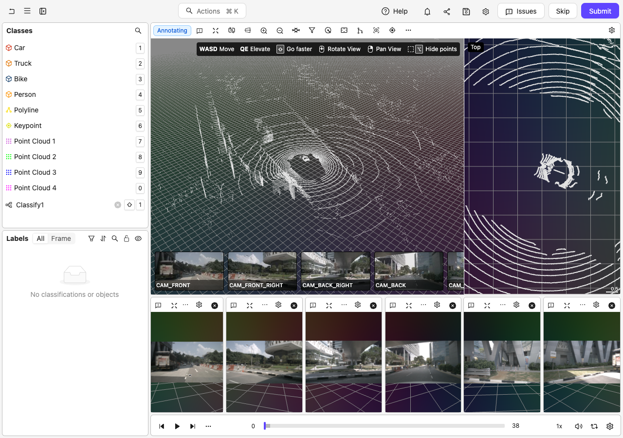
Scene-type Projects include interactive in-editor tutorials that guide you through key annotation workflows step by step. Each tutorial auto-advances as you complete actions in the editor, so you get immediate feedback as you practice on a live scene.
In-editor tutorials are only available in Scene-type (3D LiDAR/point-cloud) Projects.
The Cuboids across time tutorial teaches you the full multi-frame cuboid tracking workflow. It takes approximately 5 minutes and covers the following steps:
Select an existing cuboid in the 3D view
Copy the cuboid to the clipboard
Navigate forward several frames and place the copied cuboid using Shift + Click
Interpolate between keyframes to fill in-between frames
View the cuboid’s trajectory in the 3D view and on the timeline
Enable Auto interpolate in the editor settings so adjustments re-interpolate automatically
Edit the trajectory in grid view by dragging the cuboid in any frame column
Set the front face on the current frame using Alt + Click, or on every frame using Alt + Shift + Click
Toggle a keyframe using Alt + K
Lock the cuboid size to keep it uniform across all frames
Mark the object as static using Alt + S
The tutorial auto-advances when the editor detects you have completed each step. Step 5 (view the trajectory) requires you to click OK to advance manually. After you finish a step, you can click its title to re-expand and re-read the instructions at any time.To start the tutorial:
1
Open the Help panel
Click the Help button in the top toolbar.
2
Navigate to Tutorials
Click Tutorials in the Help panel.
3
Start the tutorial
Find the Cuboids across time card and click Start.
We strongly recommend that Taskers use a mouse when annotating or reviewing Scenes. Using a mouse makes annotating or reviewing Scenes significantly easier.
Click Start task or Initiate to annotate a PCD data unit.The Label Editor opens with a PCD data unit ready for annotation.
Use the Editor controls and Toolbar buttons to navigate the PCD workspace.
Select an object label from the left-hand menu and begin annotating the PCD data unit.
Use your input device (mouse or trackpad) to create a label in the PCD workspace.
Layouts can be configured for both MCAP recordings (Beta) and composite Scenes. Set the camera topics, 3D viewer, numeric plots, and timeline channels with the Python SDK. See MCAP layout examples for the configuration script and a visual comparison of the default and custom layouts.
Configured layout
If a Scene has a configured layout, the Label Editor uses it to arrange 3D, camera, and time-series tiles and to select time-series channels for the timeline. If the configuration only specifies timeline channels, the editor retains the default tile arrangement and adds those channels to the timeline.
Image / Video without 3D channels
For Scenes that contain image or video channels but no 3D channels, the Label Editor automatically arranges up to eight camera views in rows of up to two tiles. Channels with matching left and right names appear together first, with the left view before the right view. The remaining channels are ordered alphabetically, and an unpaired final channel appears in its own row.
Time series charts let you compare numeric telemetry with the camera and point cloud views in the same Scene. The shared playback cursor keeps the chart and sensor views aligned.
Composite Scenes: attach a CSV time series stream alongside the camera and point cloud streams when you register the Scene, then select its numeric columns in the Scene layout. Each selected column becomes a chart channel.
MCAP Scenes: select numeric sub-channels in the Scene layout. For a robot recording, this could be forward velocity (/spot/cmd_vel.linear.x) and turning velocity (/spot/cmd_vel.angular.z). The field paths depend on the recording.
Place the selected channels in the timeline to view telemetry below the sensor views, or in chart tiles to view them alongside other tiles. A layout that specifies only timeline channels keeps the default sensor arrangement above the chart.To label an event, select a Time range class and drag across its interval on the chart. For example, mark a change in velocity while inspecting the corresponding camera frames. Select the resulting range to review its boundaries and annotation attributes.See Time Series for CSV column requirements, channel customization, and a recording of the range annotation workflow.
Context-sensitive keyboard hints display in the top-right corner of the 3D view.
Move:Use the WASD keys to move along the X axis in the workspace.Elevate:Use the QE keys to move along the Y axis in the workspace.Rotate:Hold down the scroll wheel and move your mouse to rotate.Pan:Hold down the right mouse button and move your mouse to pan around.Go Faster:Hold Shift while using the WASD, QE, or camera movement keys to move faster.
Polylines appear in the orthographic side views in the side work area. Select a polyline to center the side views on its bounds and display its vertex controls. From a side view, you can:
Create a polyline by selecting its Ontology class, clicking to place each vertex, and pressing Enter to finish.
Click a segment to add a vertex, or right-click a vertex to remove it.
Drag a vertex control to move it within the side view’s plane.
Use the selected polyline’s translation and rotation controls to move or rotate it within the side view’s plane.
Click a cuboid in the 3D view to select it. If one cuboid is inside another, clicking the inner cuboid selects it directly while the outer cuboid is unselected. When the outer cuboid is selected, its face-dragging controls take precedence.To resize a selected cuboid along one axis while keeping the opposite side fixed, hold Ctrl and drag an axis handle. This works in the main 3D view, orthographic side views, camera views, and grid view, including when the cuboid has zero depth along that axis. The axis handles use square tips while resize mode is active. Cuboids with a fixed-size constraint remain in translation mode.
Smart interpolation tracks a cuboid across frames directly from the point cloud. Instead of placing the cuboid manually on every keyframe, you click a cluster of points on different frames. Encord fits a cuboid to each cluster, then uses the motion of the cluster to interpolate the object’s position on every frame in between.Smart interpolation is available for cuboid objects in Scenes.
Smart interpolation uses a fitted ground mesh to track objects accurately as the terrain rises and falls. If no ground mesh is present, the Smart interpolation panel shows a reminder to add one. Use Adjust ground to fit a ground mesh that follows the terrain before you start adding keyframes.
To track a cuboid with smart interpolation:
1
Create a cuboid keyframe
Place a cuboid on the object in at least one frame. You can draw it manually or use One-click cuboid.
2
Start smart interpolation
Right-click the cuboid and select Smart interpolation (the magic-wand icon) from the context menu. The Smart interpolation panel opens.
Smart interpolation is only available for a single, unlocked cuboid on an editable label in a Scene. It is not available for locked or approved labels, or in review and view-only modes.
3
Add keyframes by clicking clusters
Move to another frame and click a cluster of points that belongs to the object. Encord adds a keyframe and fits a cuboid to that cluster. Repeat on as many frames as you need — the more keyframes you add, the more closely the track follows the object.
Expand Show how-to in the panel for an illustrated reminder: Click a cluster of points to add a keyframe. Right-click a new keyframe to remove it.
4
Adjust and finish
Fine-tune any keyframe (see below), then click Finish to write the interpolated track to the object. Finish becomes available once you have at least two keyframes. To leave without saving, click Close (the X in the panel).
Adjust keyframes in the interpolation preview:When a cuboid keyframe is active in the interpolation preview, use the standard cuboid controls to move, resize, or rotate it. Translation is available on all three axes, so the cuboid is not restricted to the ground plane. You can also use the keyboard shortcuts shown in the top-right corner of the 3D view, including R to switch between translation and rotation and X, Y, or Z to constrain the adjustment to an axis.Enabled orthographic side views track the current preview cuboid on both keyframes and interpolated frames, helping you inspect its fit from multiple angles as you move through the preview.Lock the cuboid size:By default, smart interpolation can resize the cuboid to fit the cluster on each keyframe. To keep the cuboid a consistent size across the whole track — useful for rigid objects such as vehicles — click the Lock size toggle (the padlock icon) in the top-right of the panel. Click it again to unlock. The size lock is stored per object, so it is remembered the next time you interpolate that cuboid.Remove a keyframe:To remove a keyframe you added during smart interpolation, right-click it. The remaining keyframes are re-interpolated automatically.
When you select a cuboid and navigate to any frame where it has no annotation, the 3D view displays a ghost cuboid and keeps the cuboid pane open. Click the ghost to accept its displayed position, drag it to adjust the position before placing it, or hold Shift to preview it at the pointer and click to place it. Before placing the cuboid, press R or T to rotate it in opposite directions in 5-degree steps. Each placement method creates a keyframe for the selected cuboid on that frame. Between existing keyframes, the ghost uses the interpolated position, orientation, and size. Before the first keyframe or after the last keyframe, it uses the geometry from that nearest keyframe. The full trajectory remains visible while you position the ghost, and the path through the ghost updates as you drag it or preview placement with Shift. The ghost updates when you edit or undo changes to the surrounding keyframes.
When you work in grid view with a cuboid selected, the top-down (bird’s-eye) tile displays the selected cuboid’s full trajectory path as a semi-transparent gray line. This gives you a spatial reference for the object’s direction of travel across all frames, making it easier to verify and correct cuboid orientation without switching back to the main 3D view.The grid-view timeline shows the frame ranges for the selected cuboid. While grid view is open, playback and frame navigation stay between the cuboid’s first and last annotated frames. Use the frame skip control to move by one frame for precise adjustments or by five frames to move one grid window at a time. In an MCAP Scene, grid columns and frame steps follow the timeline snap mode rather than fixed frames. See Timeline Snapping.
The selected cuboid’s trajectory path appears regardless of the Show Cuboid Trajectories setting. The setting controls whether other eligible cuboid trajectories also appear in the main 3D view. In grid view, the selected path only appears in the top-down tile; it does not appear in side-view tiles (front, back, left, right) or camera-view tiles.
Use the trajectory overlay in the top-down grid tile to spot heading errors across keyframes — for example, when a vehicle’s cuboid orientation does not match its direction of travel. You can correct the orientation directly in grid view without switching back to the main 3D view.
Copy labels from within the same frame using Command + C and Command + Shift + V on Mac, or Ctrl + C and Ctrl + Shift + V on Windows.You can select multiple cuboids, copy them as a group, and paste them all at once onto any frame. The copied group moves together as a preview that follows your cursor, preserving each cuboid’s relative position and orientation.Enable Permanent drawing (existing instances) in the Drawing settings to streamline copying cuboids across frames. Paste with Ctrl + V on Windows or Command + V on Mac to extend the existing instances and advance by the configured Frame skip interval. You can then place the copied cuboids again with Shift + Click, and the Label Editor advances by the same interval after each placement. To create new instances on the same frame without advancing, use Ctrl + Shift + V on Windows or Command + Shift + V on Mac.
Only cuboid objects are included in a bulk copy/paste. If your multi-selection includes non-cuboid objects (such as polygons or polylines), those objects are not copied.
The stereo cuboid tool provides an assisted workflow for creating and editing 3D cuboid annotations using camera image data. The stereo tool button, Edit in stereo mode context-menu option, and associated keyboard shortcuts are available in any Scene that contains at least one image or video channel.
The stereo cuboid tool is available for Scene-type datasets only. It requires edit permissions on the label and is not available on approved labels.
The stereo tool checks calibration data for each image at fit time. If your single camera image lacks calibration data, the tool may be available but the stereo fit could fail. Ensure your image has valid calibration data for best results.
If you work with wide-angle or fisheye camera lenses and camera tiles appear cropped, enable Render full camera image in the Editor settings panel to display the full captured area.
Edit in stereo modeTo edit an existing cuboid in stereo mode, right-click the cuboid annotation and select Edit in stereo mode from the context menu. This option is available in any Scene with at least one image or video channel.Drag a seeded corner in one camera view to update the cuboid preview. The matching untouched corner in another camera view follows the fitted cuboid, reducing the number of adjustments you need to make. If you then drag that matching corner, it becomes an independent observation for the fit. The tool gives your moved or added points more influence than untouched seeded points, can fit a cuboid with zero depth, and omits corners on faces viewed at angles that are too shallow for reliable placement.
You can merge two or more 3D segmentations of the same Ontology class into one object. Select the segmentations in the timeline or the left sidebar, right-click the selection, and choose Merge segmentations into or Merge into. Then select the segmentation that you want to keep as the target.The target keeps its object identity and class, and its segmentation includes all points from the merged objects. The other objects are removed.
The Scene slicer isolates point cloud data so you can focus on a region and prevent points outside it from being selected for annotation. Click Isolate points in the 3D scene toolbar, then choose one of the following tools:
Box: Drag a box around the points you want to keep.
Polygon: Click around the points you want to keep, then press Enter or click Submit to close the polygon.
Split: Click two points to draw a line, then click the side you want to keep.
You can combine up to six slices. Use Reset in the Isolate points pane to remove all slices, or use undo and redo to step through individual slicing changes. A polygon can contain up to 24 points.
Press Escape to close the Filters, Adjust ground, or Isolate points pane. If you are fitting a ground plane from three points, the first press cancels the fit and leaves Adjust ground open; press Escape again to close the pane.
You can show or hide the orientation of cuboids using the “cuboid orientation” setting:You can change the front face of a cuboid on the current frame by holding Alt (on Windows) or Option (on Mac) and clicking any face of the cuboid. The frame becomes a keyframe, and automatic orientation from motion does not override your selection during the current editor session. After you reopen the editor, a later automatic trajectory update may change that frame. This works whether the cuboid is selected or unselected.When you hold Alt / Option, the drag-handle controls hide automatically so your click targets the cuboid face rather than a resize handle.
To change the front face across every frame where the cuboid exists, hold Alt+Shift (on Windows) or Option+Shift (on Mac) while clicking a face. Interpolated frames retain their interpolated status.
Click Filters in the toolbar to filter points by motion or height.
Color filter
The Color filter button appears in the 3D scene editor toolbar only when the loaded point cloud contains color or intensity data.
The color filter applies globally to all loaded point clouds in the scene. When you enable the filter, points outside the selected range are hidden in the viewport and cannot be selected by any segmentation tool.
Enabling the filterClick the Color filter button in the toolbar to toggle the filter on or off.Filter modesOpen the Color filter popover (click the chevron next to the button) to configure the filter. Select a mode using the mode selector at the top of the popover:
RGB — Filter points by red, green, and blue channel ranges (0–255 per channel). Available with Provided, Image color, and Sensor point cloud color modes.
HSV — Filter points by hue, saturation, and value ranges. Available with Provided, Image color, and Sensor point cloud color modes.
Intensity — Filter points by intensity range (0–100%). Available when the point cloud contains intensity data.
Use the range sliders to set the minimum and maximum values for each channel. Only points whose color or intensity falls within all specified ranges remain visible.RGB and HSV filtering uses the colors displayed by the active point cloud color mode. It is unavailable with Solid and Height. Use the height filter to filter points by height. Changing the point cloud color mode resets the RGB and HSV filter ranges.When filtering by intensity while point intensity is not displayed, the editor prompts you to enable Display point intensity in the scene settings.Eyedropper (Pick color from scene)Click Pick color from scene in the popover to activate the eyedropper. Then click any point in the 3D viewport to seed the filter with that point’s color or intensity. The sliders update automatically to a range centered on the sampled value.Composition with other filtersThe color filter works together with the height filter and slicer planes. A point must pass all active filters to remain visible and selectable.Segmentation tool integrationWhen the color filter is active, the lasso, brush, and cuboid segmentation tools automatically exclude filtered-out points from selection. Only visible points can be selected.
If the cuboid tool cannot resolve a point cloud in the rendered scene, it falls back to unfiltered selection for that cloud.
Under Motion, use Show dynamic points and Show static points to control which point classes the editor displays. When you change either setting for the first time, the editor analyzes the scene to classify its points.
The height filter lets you restrict which points the editor displays and which points segmentation tools can select, based on each point’s height above a reference surface.
The height filter offers two reference modes. The mode selector label updates dynamically depending on which ground reference is currently active:
Mode
When available
Description
Ground plane
Always
Measures each point’s height relative to the flat (or tilted) ground plane. The label changes to Ground mesh when a fitted ground mesh is active.
Ground mesh
Only when a fitted ground mesh is active
Measures each point’s height above the local mesh surface rather than a flat plane. Use this mode for curved roads, slopes, and uneven terrain.
World axes
Always
Measures each point’s height along the world vertical axis, ignoring any ground plane tilt or ground mesh.
The Ground mesh option appears in the mode selector when you activate the automatically detected mesh using Adjust ground → Use ground mesh. If no ground mesh is active, the selector shows Ground plane instead.
Click Adjust ground in the toolbar, then click Use ground mesh when the automatically detected mesh is ready.
2
Open the height filter
In the Adjust ground pane, click Open filters, then expand Height.
3
Select Ground mesh mode
In the mode selector, click Ground mesh. The histogram and min/max range update to reflect heights above the mesh surface.
4
Set your height bounds
Drag the slider or type values into the Min and Max inputs to define the height range you want to keep visible. To hide points identified as ground, click Remove ground. This sets the minimum height from the fitted mesh’s detected ground level.
Lasso (freehand) and brush segmentation tools respect the ground-mesh-relative height filter when Ground mesh mode is active. Only points above the mesh surface within your defined range are selectable.
The height filter range initializes to the 0.5th–99.5th percentile of point heights in the scene, giving you a wider default range that includes more of the point cloud.
Label branches let you keep multiple versions of a Project’s labels side-by-side. Use them to preserve a labeled state before a re-labeling pass, run an experiment without disturbing main, or hold a reviewer-only copy of labels.
This feature is only available to Workspace and Project Admins, and Team Managers in the REVIEW and COMPLETE Workflow stages.
To view labels from other branches:
Click the Branches button in the Label Editor header.
The branch overlay panel opens.
Select the checkboxes for the branches you want to overlay.
Each branch displays with a unique color indicator.
Click outside the panel to close it.
The selected branch labels now appear as read-only overlays in the 3D scene.
Press Alt + B to hide all overlaid branches. Press it again to restore your previous selection. If you have not selected branches in the current task, the shortcut overlays all available branches. The shortcut is unavailable when there are no branches to overlay.In Projects that use a Form layout, each selected branch’s classification answers also appear beneath the corresponding field, tagged with the branch’s name and color.
Branch label comparison is available in Review and Complete editor views — no feature flag or admin configuration required. Overlay labels are read-only. You cannot edit annotations from other branches directly in the overlay view.
Audio and text-document modalities do not yet display branch names on overlay labels. The vertical fan-out uses fixed pixel offsets and is not collision-aware; in very dense scenes with many overlapping annotations, labels from multiple branches may still be difficult to read.
Hot key: Shift + CCenters the camera on the selected object (cuboid, keypoint, or polyline). With no object selected, the camera centers on the ego frame when Follow ego is enabled and you are viewing a single frame. When Follow ego is disabled or the merged point cloud is displayed, the camera centers on the geometric center of the points.
Align camera with tile
Hot key: ALT/OPTION + TBrings the POV to the “tiles” listed in the drop-down that appears.
Adjust ground
Sets the position and rotation of the ground plane in the workspace. The ground plane is used for navigation (see “pan along ground” setting) as well as determining the initial position of cuboids.Click the ground plane icon in the toolbar to open the ground height controls:Auto-detection: Encord detects and fits a terrain-conforming ground mesh in the background as the scene loads. Click Use ground mesh when it is ready. Click Use ground plane to switch back to the flat ground plane without discarding the detected mesh.
Automatic ground segmentation is a preview capability. Advanced controls for ground mesh fitting parameters and the segmentation grid overlay are available in the debug panel for internal and developer users. Known limitations include reduced accuracy on steep slopes and uneven terrain in some configurations.
Set Manually:
Slider: Drag to adjust the ground height. The range spans from the lowest to the highest point in the point cloud along the up axis.
Visibility toggle: Show or hide the ground grid overlay in the 3D view.
Fit from 3 points: Select 3 points on any point cloud to automatically fit the ground plane. This is useful when the ground is not flat or is at an angle.
You can also enter “Fit from 3 points” mode directly using the keyboard shortcut Option + G (Mac) or Alt + G (Windows), without opening the popover first.
When fitting mode is active, the toolbar button changes to show how many points remain to be picked:
Click 3 points on the point cloud surface to define the ground plane. The counter updates as each point is picked. Click the x on the button or press Escape to cancel.When the ground plane is rotated (tilted), rotation information is displayed in the controls. Use the Reset rotation button to return the ground plane to flat.When the ground grid is visible, it is displayed as a grid in the scene:
For ground mesh fitting (an improved, terrain-conforming alternative to the flat ground plane), see the Ground mesh fitting settings below.
Radius indicators
Hot key: Option + RRadius indicators are useful guides when annotating in 3D space. For example, you might only want to annotate anything that comes within 3 meters of your object (vehicle, robot, drone). You would then use a radius of three and only annotate anything within that radius.
ON: Displays one or more radii centered on the object (vehicle, robot, drone) that captured PCD. You can select the color used for all radii.
OFF: Hides all the radii.
Follow ego
Hot key: ALT/OPTION + EClick Follow ego in the 3D toolbar to anchor the Scene origin to an eligible moving frame of reference, such as an ego vehicle. Click the button again to stop following, keep the view in place, and return the origin to the root frame.
The button appears only when the Scene contains a frame whose position changes relative to its parent.
Merged cloud point view
Hot key: ALT/OPTION + MDisplays point cloud data from multiple frames simultaneously in the workspace. When enabled, you can use the frame range controls to specify which frames to merge.
ON: Displays PCD from multiple frames at once. Adjust the frames displayed by dragging sliders in the navigation bar.
OFF: Displays the PCD for the current frame only.
When you enable merged view for the first time in a session, Encord selects an adaptive range of 11 to 101 frames based on the number of points in the current frame, or includes every frame if the Scene has fewer than 11. The range moves with the playhead and remains centered on it where the Scene boundaries allow. Drag the handles on the timeline or scroll over it to resize the range.
Show points in images
Hot key: ALT/OPTION + IDisplays point cloud data in 2D images.
Set camera target
Hot key: CONTROL + ALT/OPTION+ CSpecify the camera target on a single point in the PCD data.
Use this feature with Center content.
Scene view settings
Click Scene view settings on the right side of the 3D toolbar to display or hide elements in the PCD space.
Show control hints: Displays context-sensitive keyboard shortcut hints in the top-right corner.
Show camera switcher: Displays video views for the Scene.
Show zoom indicator: Displays zoom level information.
Show size rulers: Displays a scale ruler in the orthographic side views showing world unit measurements.
Show camera target: Displays the camera target in the 3D view.
Show ground cursor: Displays the ground-position crosshair in the 3D view.
Show camera tiles: Selects how camera tiles appear in the side work area.
Lidar visibility: Shows or hides individual LiDAR streams. Appears only when the Scene contains LiDAR streams.
Mesh visibility: Shows or hides individual mesh streams. Appears only when the Scene contains mesh streams.
The Show camera switcher and Show camera tiles settings appear only when the Scene includes camera images.The zoom indicator is always displayed in the 3D view, except in first-person mode.When the Scene includes camera images, select Camera in the side work area or press Shift + V to switch between 3D and Camera modes. Use Follow camera target in camera views to turn tracking on or off. When tracking is on, the side work area displays the camera views in which the selected cuboid is visible and focuses each view on the cuboid. If no cuboid is selected, the camera views follow the camera target. Hold Ctrl on Windows or Command on Mac while hovering over a valid point to preview that point as the target; when the preview ends, the camera views return to the camera target you set.To resize the side work area in either 3D or Camera mode, drag the vertical divider between it and the main 3D view. Centered orthographic side views automatically refit their content as you resize the area. Your chosen width is retained when you reload the Label Editor; double-click the divider to restore the default width.
Input DeviceSpecify using a mouse or trackpad to rotate or pan in the workspace.
We STRONGLY recommend using a mouse to rotate or pan in the workspace.
Pre-load dataPre-load data in the background for smoother navigation. Enabling this setting can improve performance when annotating or reviewing point cloud data.
Cuboid settings
FaceShows/Hides the “face” of cuboids in the PCD workspace.Show cuboid orientationControls how cuboid orientation appears in the PCD workspace. Select Front only to show an arrow that indicates the cuboid’s facing direction, All axes to show its three orientation axes, or None to hide orientation indicators. These indicators also appear on ghost cuboids while you preview their placement.Set front face from motionWhen enabled, Encord automatically orients the front face of a cuboid annotation based on the object’s local direction of motion whenever you add or paste a keyframe. It ignores small movements caused by annotation jitter. Encord re-orients existing keyframes for that cuboid in the same operation, except for frames where you manually set the front face during the current editor session, so undoing the action also reverts the orientation change.
This setting is disabled by default. When disabled, the front face follows how the cuboid was originally created. You can always set the front face manually at any time using Alt+Click.
Use Set front face from motion when annotating moving objects (such as vehicles or pedestrians) to keep cuboid orientations consistent with the direction of travel across all keyframes.
Setting the front face manually with Alt+ClickHold Alt and click any face of a cuboid to designate that face as the front face on the clicked frame. The frame becomes a keyframe, and automatic orientation from motion does not override your selection during the current editor session. After you reopen the editor, a later automatic trajectory update may change that frame. Hold Alt+Shift and click a face to set the front face across every frame instead. These shortcuts work whether the cuboid is selected or unselected.While you hold Alt, Encord hides the cuboid’s drag-handle controls and makes the cuboid body the click target, so you can accurately pick the intended face without accidentally resizing the cuboid.When you set the front face across every frame, keyframes update their stored rotation, and interpolated frames rotate to match but retain their interpolated status.Show Cuboid TrajectoriesEncord always renders the full trajectory path for selected cuboids across frames. Enable Show Cuboid Trajectories to also display the trajectories of other eligible cuboids. Trajectory paths appear in the main 3D view, while the selected cuboid’s path also appears in the top-down (bird’s-eye) tile of grid view. The trajectory does not appear in front, back, left, right, or camera-view tiles — only the top-down tile shows it, because the path collapses to a point or line from those angles.
Use the trajectory path in the top-down grid view tile to verify and correct cuboid orientation against the object’s actual direction of travel, especially when a vehicle or object has an incorrect heading across keyframes. You can do this without leaving grid view.
Cuboids with only a single frame of annotation have no trajectory data and display nothing.
Wireframe cuboids in camera viewsEnable this setting to display unselected cuboids as outlines in camera-image views. Encord hides edges blocked by the cuboid itself or by other visible cuboids, making overlapping and stacked cuboids easier to inspect. The outlines use the configured label edge opacity. This setting is disabled by default and is available only for Scenes with camera channels.
Helpers
GroundShows/Hides the “ground” plane as a grid in the PCD workspace.AxisShows/Hides the axis of the point of origin in the PCD workspace.CamerasShows/Hides camera helper lines to aid in annotating PCD.Frames of referenceShows/Hides frame origins and the parent-to-child connections between them in the main 3D view. Arrows point from each parent frame to its child. Hover over a frame origin to view the frame name, parent frame, position, and quaternion rotation relative to its parent.BackgroundShows/Hides the background in the PCD workspace.
Color filter
Click Filters in the 3D Label Editor Toolbar, then expand Color. The section reports when the loaded point cloud has no color or intensity data.
The color filter applies globally to all loaded point clouds in the scene. When you enable the filter, points outside the selected range are hidden in the viewport and cannot be selected by any segmentation tool.
Filter modesSelect a mode using the mode selector at the top of the section:
RGB — Filter points by red, green, and blue channel ranges (0–255 per channel). Available with Provided, Image color, and Sensor point cloud color modes.
HSV — Filter points by hue, saturation, and value ranges. Available with Provided, Image color, and Sensor point cloud color modes.
Intensity — Filter points by intensity range (0–100%). Available when the point cloud contains intensity data.
Use the range sliders to set the minimum and maximum values for each channel. Only points whose color or intensity falls within all specified ranges remain visible.RGB and HSV filtering uses the colors displayed by the active point cloud color mode. It is unavailable with Solid and Height. Use the height filter to filter points by height. Changing the point cloud color mode resets the RGB and HSV filter ranges.When filtering by intensity while point intensity is not displayed, the editor prompts you to enable Display point intensity in the scene settings.Eyedropper (Pick color from scene)Click Pick color from scene in the Color section of the Filters pane to activate the eyedropper. Then click any point in the 3D viewport to seed the filter with that point’s color or intensity. The sliders update automatically to a range centered on the sampled value.Composition with other filtersThe color filter works together with the height filter and slicer planes. A point must pass all active filters to remain visible and selectable.Segmentation tool integrationWhen the color filter is active, the lasso, brush, and cuboid segmentation tools automatically exclude filtered-out points from selection. Only visible points can be selected.
If the cuboid tool cannot resolve a point cloud in the rendered scene, it falls back to unfiltered selection for that cloud.
Mesh asset settings
When a Scene contains mesh assets, use the Scene settings to inspect their geometry and appearance:
Set Mesh appearance to Textured to display the asset’s colors, or Untextured to apply a neutral fill that makes its shape easier to inspect.
With Untextured selected, enable Faceted shading to shade each triangle separately instead of smoothing the surface.
Adjust Key light to control directional shading and Ambient light to control the even fill light. These lighting preferences persist across sessions.
Rest the pointer over a visible mesh to display its stream name and highlight that part.
These settings appear only when the Scene contains a mesh asset. They do not affect point-cloud-only Scenes.
Point cloud settings
A Scene can optionally include view settings which will be applied when opening it, such as the point cloud size and coloring mode. See Scene view settings to learn more.
Color settingsYou can change the color of point cloud data in the PCD workspace. Here are the options:
Solid: Displays points with a single uniform color.
Height: Displays points in colors based on the distance from the “ground” plane. Selecting this mode shows Height color range in the Scene settings, where you can adjust the displayed range.
You can adjust the “ground” plane using the ground height feature on the Editor toolbar.
Provided: Displays points in colors based on how they were originally captured and recorded. Available when a point cloud includes color data.
Image: Displays points in colors by projecting camera image data onto the points. Available when the scene includes cameras.
Sensor: Displays points colored by the sensor that captured them, making it easy to visually identify which sensor contributed which points in a multi-sensor setup. Available when the scene includes multiple point cloud streams.
The settings panel does not show color modes that the scene data does not support. If a saved color mode is unsupported in a scene, the point cloud renders using Solid.The Display point intensity setting appears only when a point cloud in the Scene includes intensity data. The sRGB color correction setting appears only when the Scene includes provided point-cloud colors and Provided is the active color mode. Render full camera image appears only when the Scene includes camera images.
When you enable Color by sensor mode, points from different sensors are automatically assigned distinct colors from a fixed palette of 20 maximally distinct colors.
Sensor colors are assigned consistently based on the sensor’s stream ID, so the same sensor is always use the same color across different frames and sessions.
PCD display settingsYou can change the display settings of point cloud data in the PCD workspace. Here are the options:
Show: Displays point cloud data in the PCD workspace.
Merge: Displays all point cloud data across time in the PCD workspace.
Hide segmented: Hides all point cloud data that is behind segmented objects in the PCD workspace.
Only segmented objects that are set to be hidden hide all point cloud data behind them.
Hide Unsegmented: Hides all points not covered by any segmentation label. This toggle is off by default. You can also toggle this setting using Shift+U.
When you enable Hide Unsegmented before creating any segmentations, no points are hidden because no segmentation coverage exists yet.
You can combine Hide Unsegmented with Hide segmented to show only points that belong to visible segmentation labels.
Use Hide Unsegmented when trimming or refining segmentations on large point cloud scenes — hiding background points reduces visual clutter and prevents the brush and lasso tools from accidentally selecting unlabeled points.
Point cloud size
Specify the size of cloud data points in the PCD workspace.
Point cloud opacity in 2D views
Specifies the opacity of PCD in 2D views.
The default value is 0. PCD does not display in 2D views with a value of 0.
Render full camera image
Renders the full image captured by the camera beyond the source image’s nominal bounds. Enable this setting when working with wide-angle or fisheye lenses in 3D scenes to display the complete captured area in the rectified camera view.
This setting is off by default. When disabled, the rectified camera view clips to the source image’s nominal bounds. This setting is only visible when you are working in a 3D scene context.
Enable Render full camera image when your camera tiles appear cropped. You can also search for this setting in the settings panel using keywords such as “fisheye”, “wide-angle”, “distortion”, “rectified”, or “clip”.
Ground mesh fitting
The ground mesh fitting tool improves ground detection in LiDAR/point cloud scenes, including curved roads and uneven terrain. Encord automatically detects and fits the mesh in the background as the scene loads. You can then activate it as an overlay in the 3D viewer, giving you a visual reference for scene geometry and making it easier to focus on objects of interest.Ground segmentationEncord automatically segments the point cloud into ground and non-ground points as the scene loads. Click Adjust ground in the toolbar, then Use ground mesh when the detected mesh is ready. To switch back without discarding the detected mesh, click Use ground plane. The segmentation algorithm handles curved and uneven terrain more accurately than a flat ground plane.Height filter integrationWhen you fit a ground mesh, the Height section of the Filters panel gains a Ground mesh mode. In this mode, the height filter measures each point’s height above the local mesh surface rather than a flat plane, enabling accurate filtering over curved or uneven terrain such as cambered roads or hilly ground.To use the height filter with a fitted ground mesh:
Click Adjust ground in the toolbar, then click Use ground mesh when the detected mesh is ready.
Close the Adjust ground pane.
Click Filters in the toolbar, then expand Height.
Select Ground mesh from the mode selector. The selector shows Ground mesh when a fitted mesh is active, or Ground plane when only a flat ground plane is available.
Adjust the Min and Max bounds. The histogram and range reflect heights above the mesh surface.
The Ground mesh option appears in the height filter mode selector only when a fitted ground mesh is active. If no ground mesh has been fitted, the selector shows Ground plane instead.
Click Remove ground to set the minimum height from the fitted mesh’s detected ground level and hide points identified as ground.Lasso (freehand) and brush segmentation tools respect the ground-mesh-relative height filter when Ground mesh mode is active, so only points above the mesh surface at the specified height range are included in your selection.To open or close the Filters panel, press F. Use the reset button beside Height to clear the height filter.When you select a cuboid and click Level, Encord aligns the cuboid with the local slope of the active ground mesh. If you use the ground plane instead, Level aligns the cuboid with that plane. The action preserves the cuboid’s position, size, and heading.
Cuboid fitting on the ground plane currently uses the flat ground plane, not the terrain mesh. Full integration with the terrain mesh is planned for a future release.
Ground mesh fitting runs in the browser. On large or merged point clouds, the fitting process may temporarily affect UI responsiveness while it completes.
Faded point opacity
Specifies the opacity of data points that fade into the background. For example, all data points outside of a Scene slice.
Color points inside cuboids
Controls whether points that fall inside cuboids are highlighted with special coloring to make them more visible. This setting overrides the normal point coloring mode for points contained within cuboid annotations.
Option
Description
All cuboids
Highlights points inside every cuboid annotation (default behavior).
Selected only
Only highlights points inside the currently selected cuboid.
None
Disables cuboid point highlighting entirely.
Use “Selected only” mode when working with many overlapping cuboids to focus on the cuboid you’re currently editing.
Label color mode (review)
Controls how 3D labels are colored during workflow review and consensus review tasks. This setting applies to all 3D label types: cuboids, spheres, polylines, and keypoints/points.
This setting only takes effect when you are in a workflow review stage or consensus review stage. It has no effect outside of review tasks.
By review statusWhen you set Label color mode (review) to By review status, all 3D labels in the point cloud viewport are recolored according to their current review state:
Review state
Color
Pending
Orange
Approved
Green
Rejected
Red
Labels you action (approve or reject) during the current review session fade to the opacity configured in Reviewed label opacity, reducing visual clutter as you work through the scene.
The opacity fade applies only to filled shapes — cuboids and spheres. Polylines and keypoints/points are recolored by review status but do not fade.
Selected 3D labels retain their review-status fill color when selected. Only the selection outline switches to the selection highlight color, matching the behavior in 2D review tasks.
Reviewed label opacity
Specifies the opacity applied to 3D labels that you have actioned (approved or rejected) during the current review session. Reducing this value fades reviewed labels into the background, making it easier to focus on labels that still require review.
The opacity fade applies only to filled shapes — cuboids and spheres. Polylines and keypoints/points are recolored by review status but are not affected by this opacity setting.
This setting only takes effect when Label color mode (review) is set to By review status and you are in a workflow review stage or consensus review stage.
In-editor tutorials (Scene projects)
Scene-type (3D LiDAR/point-cloud) projects include interactive in-editor tutorials you can access directly from the label editor. Each tutorial guides you through a specific workflow step by step, and the editor automatically detects when you complete each action so the tutorial advances in real time.Accessing tutorialsClick the Help button in the top toolbar, then select Tutorials. The tutorials panel lists all available tutorials for your project type. Click Start on any tutorial card to begin.Cuboids across timeThe Cuboids across time tutorial teaches you the full multi-frame cuboid tracking workflow. It takes approximately 5 minutes and covers the following steps:
Select a cuboid — select an existing cuboid in the 3D view.
Copy the cuboid — copy the selected cuboid to the clipboard.
Place it on a later frame — navigate forward several frames, then hold Shift to preview the copied cuboid and click to place it.
Interpolate between keyframes — fill every frame between your two keyframes using the interpolate shortcut or the right-click menu.
View the trajectory — review the trajectory the editor draws between keyframes, then confirm with OK.
Turn on auto re-interpolation — enable Auto interpolate under Drawing in the editor settings so the editor automatically re-runs interpolation when you adjust a keyframe.
Edit the trajectory in grid view — open grid view, drag the cuboid in any frame column to refine its position, and close grid view when done.
Set the front face — use Alt+click to set the front face on the current frame, or add Shift to set it on every frame.
Toggle a keyframe — use Alt+K to unmark or re-mark the current frame as a keyframe.
Lock the size — click Lock size in the cuboid pane to enforce a uniform size across all frames.
Make it static — use Alt+S or the pushpin in the cuboid pane to mark the object as static, copying its current pose to every frame.
After you complete a step, the tutorial advances automatically. Step 5 (View the trajectory) requires you to click OK to advance manually. Once you finish a step, you can click its title to re-expand it and re-read the instructions at any time.
The Cuboids across time tutorial is only available in Scene-type (3D LiDAR/point-cloud) projects. It does not appear for other project types.


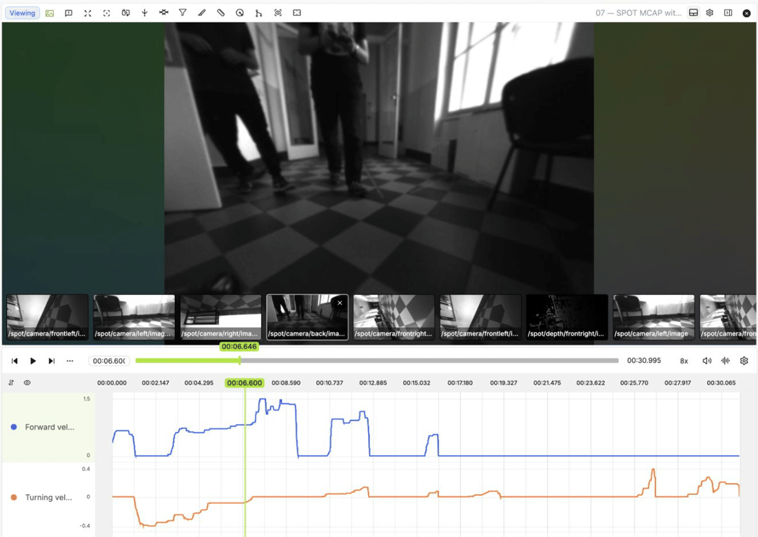 To label an event, select a Time range class and drag across its interval on the chart. For example, mark a change in velocity while inspecting the corresponding camera frames. Select the resulting range to review its boundaries and annotation attributes.
See Time Series for CSV column requirements, channel customization, and a recording of the range annotation workflow.
To label an event, select a Time range class and drag across its interval on the chart. For example, mark a change in velocity while inspecting the corresponding camera frames. Select the resulting range to review its boundaries and annotation attributes.
See Time Series for CSV column requirements, channel customization, and a recording of the range annotation workflow.

 Auto-detection: Encord detects and fits a terrain-conforming ground mesh in the background as the scene loads. Click Use ground mesh when it is ready. Click Use ground plane to switch back to the flat ground plane without discarding the detected mesh.
 Click 3 points on the point cloud surface to define the ground plane. The counter updates as each point is picked. Click the x on the button or press Escape to cancel.When the ground plane is rotated (tilted), rotation information is displayed in the controls. Use the Reset rotation button to return the ground plane to flat.When the ground grid is visible, it is displayed as a grid in the scene: