> ## Documentation Index
> Fetch the complete documentation index at: https://docs.encord.com/llms.txt
> Use this file to discover all available pages before exploring further.
# Annotating Scenes
We strongly recommend enabling [graphics acceleration](https://www.howtogeek.com/412738/how-to-turn-hardware-acceleration-on-and-off-in-chrome/#:~:text=In%20the%20Settings%20menu%2C%20expand,Relaunch%E2%80%9D%20to%20apply%20the%20changes) in Chrome when working with PCD Scenes.
## In-Editor Tutorials
Scene-type Projects include interactive in-editor tutorials that guide you through key annotation workflows step by step. Each tutorial auto-advances as you complete actions in the editor, so you get immediate feedback as you practice on a live scene.
In-editor tutorials are only available in Scene-type (3D LiDAR/point-cloud) Projects.
### Cuboids across time
The **Cuboids across time** tutorial teaches you the full multi-frame cuboid tracking workflow. It takes approximately 5 minutes and covers 10 steps:
1. Select an existing cuboid in the 3D view
2. Copy the cuboid to the clipboard
3. Navigate forward several frames and place the copied cuboid using `Shift + Click`
4. Interpolate between keyframes to fill in-between frames
5. View the cuboid's trajectory in the 3D view and on the timeline
6. Enable **Auto interpolate** in the editor settings so adjustments re-interpolate automatically
7. Edit the trajectory in grid view by dragging the cuboid in any frame column
8. Toggle a keyframe using `Alt + K`
9. Lock the cuboid size to keep it uniform across all frames
10. Mark the object as static using `Alt + S`
The tutorial auto-advances when the editor detects you have completed each step. Step 5 (view the trajectory) requires you to click **OK** to advance manually. After you finish a step, you can click its title to re-expand and re-read the instructions at any time.
**To start the tutorial:**
Click the **Help** button in the top toolbar.
Click **Tutorials** in the Help panel.
Find the **Cuboids across time** card and click **Start**.
***
# Label and Review Scenes
We strongly recommend that Taskers use a mouse when annotating or reviewing Scenes. Using a mouse makes annotating or reviewing Scenes significantly easier.
1. Click **Start task** or **Initiate** to annotate a PCD data unit.
The Label Editor opens with a PCD data unit ready for annotation.
2. Use the Editor controls and Toolbar buttons to navigate the PCD workspace.
3. Select an object label from the left-hand menu and begin annotating the PCD data unit.
4. Use your input device (mouse or trackpad) to create a label in the PCD workspace.
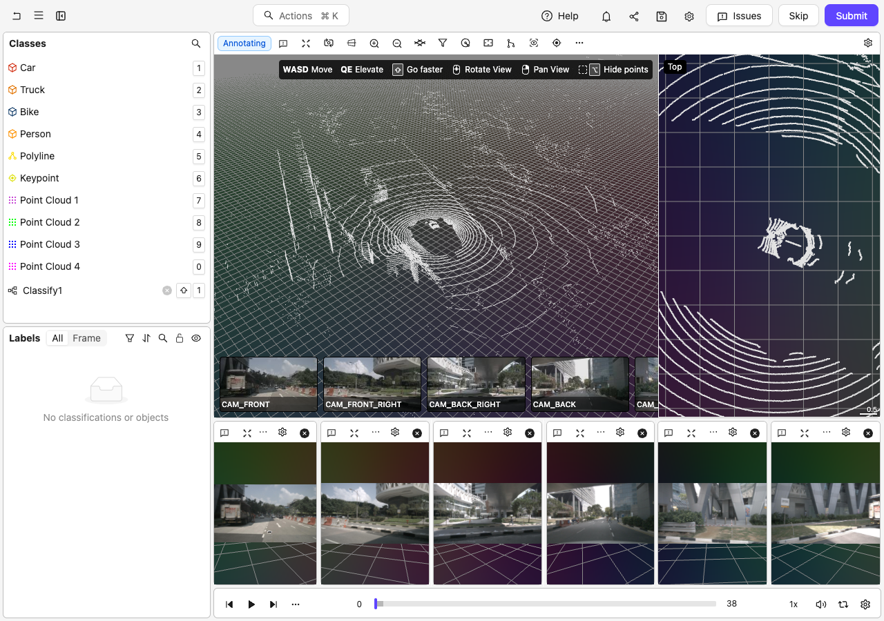
# Navigating in the Scene
Context-sensitive keyboard hints display in the top-right corner of the 3D view.
**Move**:
Use the WASD keys to move along the X axis in the workspace.
**Elevate**:
Use the QE keys to move along the Y axis in the workspace.
**Rotate**:
Hold down the scroll wheel and move your mouse to rotate.
**Pan**:
Hold down the right mouse button and move your mouse to pan around.
**Go Faster**:
Hold Shift while using the WASD, QE, or camera movement keys to move faster.
# Annotations
## Cuboids
### Copy and pasting Cuboids
Copy labels from within the same frame using Command + C and Command + Shift + V on Mac, or Ctrl + C and Ctrl + Shift + V on Windows.
You can select multiple cuboids, copy them as a group, and paste them all at once onto any frame. The copied group moves together as a preview that follows your cursor, preserving each cuboid's relative position and orientation.
Only cuboid objects are included in a bulk copy/paste. If your multi-selection includes non-cuboid objects (such as polygons or polylines), those objects are not copied.
Copy/paste keyboard shortcuts:
| Action | Windows | Mac |
| --------------------------------- | -------------------------------------- | ----------------------------------------- |
| Copy selected cuboid(s) | Ctrl + C | Command + C |
| Place copied cuboid(s) | Shift + Click | Shift + Click |
| Yaw-rotate group before placement | R | R |
| Select all cuboids | Ctrl + A | Command + A |
| Clear clipboard | Ctrl + C (nothing selected) | Command + C (nothing selected) |
## Stereo Cuboid Tool
The stereo cuboid tool provides an assisted workflow for creating and editing 3D cuboid annotations using camera image data. The stereo tool button, **Edit in stereo mode** context-menu option, and associated keyboard shortcuts are available in any Scene that contains at least one image or video channel.
The stereo cuboid tool is available for Scene-type datasets only. It requires edit permissions on the label and is not available on approved labels.
The stereo tool checks calibration data for each image at fit time. If your single camera image lacks calibration data, the tool may be available but the stereo fit could fail. Ensure your image has valid calibration data for best results.
### Stereo cuboid keyboard shortcuts
| Action | Windows | Mac |
| --------------------- | ----------------------------------------------------- | ----------------------------------------------------- |
| Activate stereo tool | Stereo hotkey (`tools:stereo`) | Stereo hotkey (`tools:stereo`) |
| Toggle stereo preview | Stereo preview toggle (`tools:stereo-preview-toggle`) | Stereo preview toggle (`tools:stereo-preview-toggle`) |
### Edit in stereo mode
To edit an existing cuboid in stereo mode, right-click the cuboid annotation and select **Edit in stereo mode** from the context menu. This option is available in any Scene with at least one image or video channel.
## Toolbar
### Setting cuboid orientation
You can show or hide the orientation of cuboids using the "cuboid orientation" setting:
You can change the front face of a cuboid by hovering over any side of the cuboid and clicking Alt (on Windows) or Option (on Mac), and then clicking a face of the cuboid.
This changes the front face of the cuboid across all the frames where it exists.
## Point Cloud Segmentation
### Scene Slicer
The Scene slicer is a planar point cloud data selection guard. Place a Scene slicer to confine point cloud data selection. Point cloud data on the outside of the Scene slicer area cannot be selected for annotation.
Use the left-click button on your mouse to select an area in the PCD workspace. Use the Alt/Option key to hide all point data outside the selected area.
# Editor actions
Hot key: Shift + C
Brings the POV to origin. When you have an object selected (cuboid, keypoint, or polyline), this command centers the camera on that object instead of the origin.
Hot key: ALT/OPTION + T
Brings the POV to the "tiles" listed in the drop-down that appears.
Sets the position and rotation of the ground plane in the workspace. The ground plane is used for navigation (see "pan along ground" setting) as well as determining the initial position of cuboids.
Click the ground plane icon in the toolbar to open the ground height controls:
 * **Slider**: Drag to adjust the ground height. The range spans from the lowest to the highest point in the point cloud along the up axis.
* **Visibility toggle**: Show or hide the ground grid overlay in the 3D view.
* **Fit from 3 points**: Select 3 points on any point cloud to automatically fit the ground plane. This is useful when the ground is not flat or is at an angle.
You can also enter "Fit from 3 points" mode directly using the keyboard shortcut Option + G (Mac) or Alt + G (Windows), without opening the popover first.
When fitting mode is active, the toolbar button changes to show how many points remain to be picked:
* **Slider**: Drag to adjust the ground height. The range spans from the lowest to the highest point in the point cloud along the up axis.
* **Visibility toggle**: Show or hide the ground grid overlay in the 3D view.
* **Fit from 3 points**: Select 3 points on any point cloud to automatically fit the ground plane. This is useful when the ground is not flat or is at an angle.
You can also enter "Fit from 3 points" mode directly using the keyboard shortcut Option + G (Mac) or Alt + G (Windows), without opening the popover first.
When fitting mode is active, the toolbar button changes to show how many points remain to be picked:
 Click 3 points on the point cloud surface to define the ground plane. The counter updates as each point is picked. Click the **x** on the button or press Escape to cancel.
When the ground plane is rotated (tilted), rotation information is displayed in the controls. Use the **Reset rotation** button to return the ground plane to flat.
When the ground grid is visible, it is displayed as a grid in the scene:
Click 3 points on the point cloud surface to define the ground plane. The counter updates as each point is picked. Click the **x** on the button or press Escape to cancel.
When the ground plane is rotated (tilted), rotation information is displayed in the controls. Use the **Reset rotation** button to return the ground plane to flat.
When the ground grid is visible, it is displayed as a grid in the scene:
 ### Ground mesh fitting
Ground mesh fitting is available to select customers. Contact your Encord representative to request access.
The ground mesh fitting feature provides an additional **Fit ground mesh** option. This workflow uses an improved ground segmentation algorithm and a cloth-simulation-based mesh fitting step to produce a terrain-conforming ground surface. This is useful for curved roads, slopes, and uneven terrain.
**How it works:**
1. Open the ground height controls from the toolbar.
2. Select **Fit ground mesh** to open the ground mesh fitting modal.
3. Encord segments the point cloud to identify ground points. The segmentation algorithm handles curved and uneven terrain more accurately than the standard flat ground plane.
4. The editor groups similar terrain grid cells into clusters using agglomerative clustering. You can classify groups of similar cells together in bulk rather than one at a time.
5. Once you confirm the ground classification, Encord fits a cloth-simulation mesh over the identified ground points, producing a terrain-hugging ground surface.
Cuboid fitting on the ground plane currently uses the standard flat ground plane, not the terrain mesh. Full integration of the terrain mesh with cuboid fitting is planned for a future update.
Hot key: Option + R
Radius indicators are useful guides when annotating in 3D space. For example, you might only want to annotate anything that comes within 3 meters of your object (vehicle, robot, drone). You would then use a radius of three and only annotate anything within that radius.
* `ON`: Displays one or more radii centered on the object (vehicle, robot, drone) that captured PCD. You can select the color used for all radii.
* `OFF`: Hides all the radii.
Specify custom or use "tile" coordinates as the Scene origin.
Hot key: ALT/OPTION + M
Displays point cloud data from multiple frames simultaneously in the workspace. When enabled, you can use the frame range controls to specify which frames to merge.
* `ON`: Displays PCD from multiple frames at once. Click the dropdown arrow next to the button to access the controls.
* `OFF`: Displays the PCD for the current frame only.
By default, all frames in the scene are included when merged view is enabled.
Hot key: ALT/OPTION + I
Displays point cloud data in 2D images.
Hot key: CONTROL + ALT/OPTION+ C
Specify the camera target on a single point in the PCD data.
Use this feature with *Center camera on orign*.
Display or hide various elements in the PCD space.
* `Show top view`: Displays view from the top in the right hand work area.
* `Show left view`: Displays view from the left in the right hand work area.
* `Show right view`: Displays view from the right in the right hand work area.
* `Show control hints`: Displays context-sensitive keyboard shortcut hints in the top-right corner.
* `Show camera switcher`: Displays video views for the Scene.
* `Show zoom indicator`: Displays zoom level information.
* `Show size rulers`: Displays a scale ruler in the orthographic side views showing world unit measurements.
***
# Editor Settings
**Input Device**
Specify using a `mouse` or `trackpad` to rotate or pan in the workspace.
We **STRONGLY** recommend using a mouse to rotate or pan in the workspace.
**Pre-load data**
Pre-load data in the background for smoother navigation. Enabling this setting can improve performance when annotating or reviewing point cloud data.
***
**Face**
Shows/Hides the "face" of cuboids in the PCD workspace.
**Orientation**
Shows/Hides the orientation of cuboids in the PCD workspace.
**Set front face from motion**
When enabled, Encord automatically orients the front face of a cuboid annotation based on the object's direction of motion whenever you add or paste a keyframe. Encord re-orients all existing keyframes for that cuboid in the same operation, so undoing the action also reverts the orientation change.
This setting is disabled by default. When disabled, the front face follows how the cuboid was originally created. You can always set the front face manually at any time using `Alt+Click`.
Use **Set front face from motion** when annotating moving objects (such as vehicles or pedestrians) to keep cuboid orientations consistent with the direction of travel across all keyframes.
**Ground**
Shows/Hides the "ground" plane as a grid in the PCD workspace.
**Axis**
Shows/Hides the axis of the point of origin in the PCD workspace.
**Cameras**
Shows/Hides camera helper lines to aid in annotating PCD.
**Background**
Shows/Hides the background in the PCD workspace.
**Color settings**
You can change the color of point cloud data in the PCD workspace. Here are the options:
* **Solid**: Displays points with a single uniform color.
* **Origin**: Displays points in colors based on the distance from the world origin point.
* **Camera**: Displays points in colors based on the distance from the camera position.
* **Height**: Displays points in colors based on the distance from the "ground" plane.
You can adjust the "ground" plane using the [ground height]() feature on the Editor toolbar.
* **Provided**: Displays points in colors based on how they were originally captured and recorded.
* **Image**: Displays points in colors by projecting camera image data onto the points.
* **Sensor**: Displays points colored by the sensor that captured them, making it easy to visually identify which sensor contributed which points in a multi-sensor setup.
- When you enable **Color by sensor** mode, points from different sensors are automatically assigned distinct colors from a fixed palette of 20 maximally distinct colors.
- Sensor colors are assigned consistently based on the sensor's stream ID, so the same sensor is always use the same color across different frames and sessions.
**PCD display settings**
You can change the display settings of point cloud data in the PCD workspace. Here are the options:
* Show: Displays point cloud data in the PCD workspace.
* Merge: Displays all point cloud data across time in the PCD workspace.
* Uniform size: Displays all point cloud data in a uniform size in the PCD workspace.
* Hide segmented: Hides all point cloud data that is behind segmented objects in the PCD workspace.
Only segmented objects that are set to be hidden hide all point cloud data behind them.
Specify the size of cloud data points in the PCD workspace.
Specifies the opacity of PCD in 2D views.
The default value is 0. PCD does not display in 2D views with a value of 0.
Ground mesh fitting is available to select customers. Contact your Encord representative to request access.
The ground mesh fitting tool improves ground detection for LiDAR/point cloud scenes, including curved roads and uneven terrain. When enabled, the tool fits a terrain-conforming mesh over the ground points Encord detects in the scene.
**Ground segmentation**
Encord automatically segments the point cloud into ground and non-ground points. The segmentation algorithm handles curved and uneven terrain more accurately than a flat ground plane.
**Terrain clustering**
Encord groups similar terrain grid cells together using agglomerative clustering. You can classify groups of similar cells in bulk rather than one cell at a time, speeding up ground classification on complex terrain.
**Cloth-simulation mesh fitting**
After you classify the ground points, Encord drapes a mesh over them using a cloth-simulation algorithm. The resulting mesh conforms to the terrain surface and provides a more accurate ground reference for downstream annotation tasks.
Cuboid fitting on the ground plane currently uses the flat ground plane, not the terrain mesh. Full integration with the terrain mesh is planned for a future release.
Specifies the opacity of data points that fade into the background. For example, all data points outside of a Scene slice.
Controls whether points that fall inside cuboids are highlighted with special coloring to make them more visible. This setting overrides the normal point coloring mode for points contained within cuboid annotations.
| Option | Description |
| ----------------- | -------------------------------------------------------------------- |
| **All cuboids** | Highlights points inside every cuboid annotation (default behavior). |
| **Selected only** | Only highlights points inside the currently selected cuboid. |
| **None** | Disables cuboid point highlighting entirely. |
Use "Selected only" mode when working with many overlapping cuboids to focus on the cuboid you're currently editing.
Controls how 3D labels are colored during workflow review and consensus review tasks. This setting applies to all 3D label types: cuboids, spheres, polylines, and keypoints/points.
This setting only takes effect when you are in a workflow review stage or consensus review stage. It has no effect outside of review tasks.
**By review status**
When you set **Label color mode (review)** to **By review status**, all 3D labels in the point cloud viewport are recolored according to their current review state:
| Review state | Color |
| ------------ | ------ |
| Pending | Orange |
| Approved | Green |
| Rejected | Red |
Labels you action (approve or reject) during the current review session fade to the opacity configured in **Reviewed label opacity**, reducing visual clutter as you work through the scene.
The opacity fade applies only to filled shapes — cuboids and spheres. Polylines and keypoints/points are recolored by review status but do not fade.
Selected 3D labels retain their review-status fill color when selected. Only the selection outline switches to the selection highlight color, matching the behavior in 2D review tasks.
Specifies the opacity applied to 3D labels that you have actioned (approved or rejected) during the current review session. Reducing this value fades reviewed labels into the background, making it easier to focus on labels that still require review.
The opacity fade applies only to filled shapes — cuboids and spheres. Polylines and keypoints/points are recolored by review status but are not affected by this opacity setting.
This setting only takes effect when **Label color mode (review)** is set to **By review status** and you are in a workflow review stage or consensus review stage.
Scene-type (3D LiDAR/point-cloud) projects include interactive in-editor tutorials you can access directly from the label editor. Each tutorial guides you through a specific workflow step by step, and the editor automatically detects when you complete each action so the tutorial advances in real time.
**Accessing tutorials**
Click the **Help** button in the top toolbar, then select **Tutorials**. The tutorials panel lists all available tutorials for your project type. Click **Start** on any tutorial card to begin.
**Cuboids across time**
The **Cuboids across time** tutorial teaches you the full multi-frame cuboid tracking workflow. It takes approximately 5 minutes and covers 10 steps:
1. **Select a cuboid** — select an existing cuboid in the 3D view.
2. **Copy the cuboid** — copy the selected cuboid to the clipboard.
3. **Place it on a later frame** — navigate forward several frames, then hold `Shift` to preview the copied cuboid and click to place it.
4. **Interpolate between keyframes** — fill every frame between your two keyframes using the interpolate shortcut or the right-click menu.
5. **View the trajectory** — review the trajectory the editor draws between keyframes, then confirm with **OK**.
6. **Turn on auto re-interpolation** — enable **Auto interpolate** under **Drawing** in the editor settings so the editor automatically re-runs interpolation when you adjust a keyframe.
7. **Edit the trajectory in grid view** — open grid view, drag the cuboid in any frame column to refine its position, and close grid view when done.
8. **Toggle a keyframe** — use `Alt`+`K` to unmark or re-mark the current frame as a keyframe.
9. **Lock the size** — click **Lock size** in the cuboid pane to enforce a uniform size across all frames.
10. **Make it static** — use `Alt`+`S` or the pushpin in the cuboid pane to mark the object as static, copying its current pose to every frame.
After you complete a step, the tutorial advances automatically. Step 5 (View the trajectory) requires you to click **OK** to advance manually. Once you finish a step, you can click its title to re-expand it and re-read the instructions at any time.
The **Cuboids across time** tutorial is only available in Scene-type (3D LiDAR/point-cloud) projects. It does not appear for other project types.
### Ground mesh fitting
Ground mesh fitting is available to select customers. Contact your Encord representative to request access.
The ground mesh fitting feature provides an additional **Fit ground mesh** option. This workflow uses an improved ground segmentation algorithm and a cloth-simulation-based mesh fitting step to produce a terrain-conforming ground surface. This is useful for curved roads, slopes, and uneven terrain.
**How it works:**
1. Open the ground height controls from the toolbar.
2. Select **Fit ground mesh** to open the ground mesh fitting modal.
3. Encord segments the point cloud to identify ground points. The segmentation algorithm handles curved and uneven terrain more accurately than the standard flat ground plane.
4. The editor groups similar terrain grid cells into clusters using agglomerative clustering. You can classify groups of similar cells together in bulk rather than one at a time.
5. Once you confirm the ground classification, Encord fits a cloth-simulation mesh over the identified ground points, producing a terrain-hugging ground surface.
Cuboid fitting on the ground plane currently uses the standard flat ground plane, not the terrain mesh. Full integration of the terrain mesh with cuboid fitting is planned for a future update.
Hot key: Option + R
Radius indicators are useful guides when annotating in 3D space. For example, you might only want to annotate anything that comes within 3 meters of your object (vehicle, robot, drone). You would then use a radius of three and only annotate anything within that radius.
* `ON`: Displays one or more radii centered on the object (vehicle, robot, drone) that captured PCD. You can select the color used for all radii.
* `OFF`: Hides all the radii.
Specify custom or use "tile" coordinates as the Scene origin.
Hot key: ALT/OPTION + M
Displays point cloud data from multiple frames simultaneously in the workspace. When enabled, you can use the frame range controls to specify which frames to merge.
* `ON`: Displays PCD from multiple frames at once. Click the dropdown arrow next to the button to access the controls.
* `OFF`: Displays the PCD for the current frame only.
By default, all frames in the scene are included when merged view is enabled.
Hot key: ALT/OPTION + I
Displays point cloud data in 2D images.
Hot key: CONTROL + ALT/OPTION+ C
Specify the camera target on a single point in the PCD data.
Use this feature with *Center camera on orign*.
Display or hide various elements in the PCD space.
* `Show top view`: Displays view from the top in the right hand work area.
* `Show left view`: Displays view from the left in the right hand work area.
* `Show right view`: Displays view from the right in the right hand work area.
* `Show control hints`: Displays context-sensitive keyboard shortcut hints in the top-right corner.
* `Show camera switcher`: Displays video views for the Scene.
* `Show zoom indicator`: Displays zoom level information.
* `Show size rulers`: Displays a scale ruler in the orthographic side views showing world unit measurements.
***
# Editor Settings
**Input Device**
Specify using a `mouse` or `trackpad` to rotate or pan in the workspace.
We **STRONGLY** recommend using a mouse to rotate or pan in the workspace.
**Pre-load data**
Pre-load data in the background for smoother navigation. Enabling this setting can improve performance when annotating or reviewing point cloud data.
***
**Face**
Shows/Hides the "face" of cuboids in the PCD workspace.
**Orientation**
Shows/Hides the orientation of cuboids in the PCD workspace.
**Set front face from motion**
When enabled, Encord automatically orients the front face of a cuboid annotation based on the object's direction of motion whenever you add or paste a keyframe. Encord re-orients all existing keyframes for that cuboid in the same operation, so undoing the action also reverts the orientation change.
This setting is disabled by default. When disabled, the front face follows how the cuboid was originally created. You can always set the front face manually at any time using `Alt+Click`.
Use **Set front face from motion** when annotating moving objects (such as vehicles or pedestrians) to keep cuboid orientations consistent with the direction of travel across all keyframes.
**Ground**
Shows/Hides the "ground" plane as a grid in the PCD workspace.
**Axis**
Shows/Hides the axis of the point of origin in the PCD workspace.
**Cameras**
Shows/Hides camera helper lines to aid in annotating PCD.
**Background**
Shows/Hides the background in the PCD workspace.
**Color settings**
You can change the color of point cloud data in the PCD workspace. Here are the options:
* **Solid**: Displays points with a single uniform color.
* **Origin**: Displays points in colors based on the distance from the world origin point.
* **Camera**: Displays points in colors based on the distance from the camera position.
* **Height**: Displays points in colors based on the distance from the "ground" plane.
You can adjust the "ground" plane using the [ground height]() feature on the Editor toolbar.
* **Provided**: Displays points in colors based on how they were originally captured and recorded.
* **Image**: Displays points in colors by projecting camera image data onto the points.
* **Sensor**: Displays points colored by the sensor that captured them, making it easy to visually identify which sensor contributed which points in a multi-sensor setup.
- When you enable **Color by sensor** mode, points from different sensors are automatically assigned distinct colors from a fixed palette of 20 maximally distinct colors.
- Sensor colors are assigned consistently based on the sensor's stream ID, so the same sensor is always use the same color across different frames and sessions.
**PCD display settings**
You can change the display settings of point cloud data in the PCD workspace. Here are the options:
* Show: Displays point cloud data in the PCD workspace.
* Merge: Displays all point cloud data across time in the PCD workspace.
* Uniform size: Displays all point cloud data in a uniform size in the PCD workspace.
* Hide segmented: Hides all point cloud data that is behind segmented objects in the PCD workspace.
Only segmented objects that are set to be hidden hide all point cloud data behind them.
Specify the size of cloud data points in the PCD workspace.
Specifies the opacity of PCD in 2D views.
The default value is 0. PCD does not display in 2D views with a value of 0.
Ground mesh fitting is available to select customers. Contact your Encord representative to request access.
The ground mesh fitting tool improves ground detection for LiDAR/point cloud scenes, including curved roads and uneven terrain. When enabled, the tool fits a terrain-conforming mesh over the ground points Encord detects in the scene.
**Ground segmentation**
Encord automatically segments the point cloud into ground and non-ground points. The segmentation algorithm handles curved and uneven terrain more accurately than a flat ground plane.
**Terrain clustering**
Encord groups similar terrain grid cells together using agglomerative clustering. You can classify groups of similar cells in bulk rather than one cell at a time, speeding up ground classification on complex terrain.
**Cloth-simulation mesh fitting**
After you classify the ground points, Encord drapes a mesh over them using a cloth-simulation algorithm. The resulting mesh conforms to the terrain surface and provides a more accurate ground reference for downstream annotation tasks.
Cuboid fitting on the ground plane currently uses the flat ground plane, not the terrain mesh. Full integration with the terrain mesh is planned for a future release.
Specifies the opacity of data points that fade into the background. For example, all data points outside of a Scene slice.
Controls whether points that fall inside cuboids are highlighted with special coloring to make them more visible. This setting overrides the normal point coloring mode for points contained within cuboid annotations.
| Option | Description |
| ----------------- | -------------------------------------------------------------------- |
| **All cuboids** | Highlights points inside every cuboid annotation (default behavior). |
| **Selected only** | Only highlights points inside the currently selected cuboid. |
| **None** | Disables cuboid point highlighting entirely. |
Use "Selected only" mode when working with many overlapping cuboids to focus on the cuboid you're currently editing.
Controls how 3D labels are colored during workflow review and consensus review tasks. This setting applies to all 3D label types: cuboids, spheres, polylines, and keypoints/points.
This setting only takes effect when you are in a workflow review stage or consensus review stage. It has no effect outside of review tasks.
**By review status**
When you set **Label color mode (review)** to **By review status**, all 3D labels in the point cloud viewport are recolored according to their current review state:
| Review state | Color |
| ------------ | ------ |
| Pending | Orange |
| Approved | Green |
| Rejected | Red |
Labels you action (approve or reject) during the current review session fade to the opacity configured in **Reviewed label opacity**, reducing visual clutter as you work through the scene.
The opacity fade applies only to filled shapes — cuboids and spheres. Polylines and keypoints/points are recolored by review status but do not fade.
Selected 3D labels retain their review-status fill color when selected. Only the selection outline switches to the selection highlight color, matching the behavior in 2D review tasks.
Specifies the opacity applied to 3D labels that you have actioned (approved or rejected) during the current review session. Reducing this value fades reviewed labels into the background, making it easier to focus on labels that still require review.
The opacity fade applies only to filled shapes — cuboids and spheres. Polylines and keypoints/points are recolored by review status but are not affected by this opacity setting.
This setting only takes effect when **Label color mode (review)** is set to **By review status** and you are in a workflow review stage or consensus review stage.
Scene-type (3D LiDAR/point-cloud) projects include interactive in-editor tutorials you can access directly from the label editor. Each tutorial guides you through a specific workflow step by step, and the editor automatically detects when you complete each action so the tutorial advances in real time.
**Accessing tutorials**
Click the **Help** button in the top toolbar, then select **Tutorials**. The tutorials panel lists all available tutorials for your project type. Click **Start** on any tutorial card to begin.
**Cuboids across time**
The **Cuboids across time** tutorial teaches you the full multi-frame cuboid tracking workflow. It takes approximately 5 minutes and covers 10 steps:
1. **Select a cuboid** — select an existing cuboid in the 3D view.
2. **Copy the cuboid** — copy the selected cuboid to the clipboard.
3. **Place it on a later frame** — navigate forward several frames, then hold `Shift` to preview the copied cuboid and click to place it.
4. **Interpolate between keyframes** — fill every frame between your two keyframes using the interpolate shortcut or the right-click menu.
5. **View the trajectory** — review the trajectory the editor draws between keyframes, then confirm with **OK**.
6. **Turn on auto re-interpolation** — enable **Auto interpolate** under **Drawing** in the editor settings so the editor automatically re-runs interpolation when you adjust a keyframe.
7. **Edit the trajectory in grid view** — open grid view, drag the cuboid in any frame column to refine its position, and close grid view when done.
8. **Toggle a keyframe** — use `Alt`+`K` to unmark or re-mark the current frame as a keyframe.
9. **Lock the size** — click **Lock size** in the cuboid pane to enforce a uniform size across all frames.
10. **Make it static** — use `Alt`+`S` or the pushpin in the cuboid pane to mark the object as static, copying its current pose to every frame.
After you complete a step, the tutorial advances automatically. Step 5 (View the trajectory) requires you to click **OK** to advance manually. Once you finish a step, you can click its title to re-expand it and re-read the instructions at any time.
The **Cuboids across time** tutorial is only available in Scene-type (3D LiDAR/point-cloud) projects. It does not appear for other project types.